3D Assembly Viewer
For multi-board projects, the 3D viewer can render every sub-board together as a single assembly. Launch via View → 3D Assembly Viewer from the multi-board schematic editor. The viewer loads each sub-board's 3D model and places them according to the container's assembly metadata.
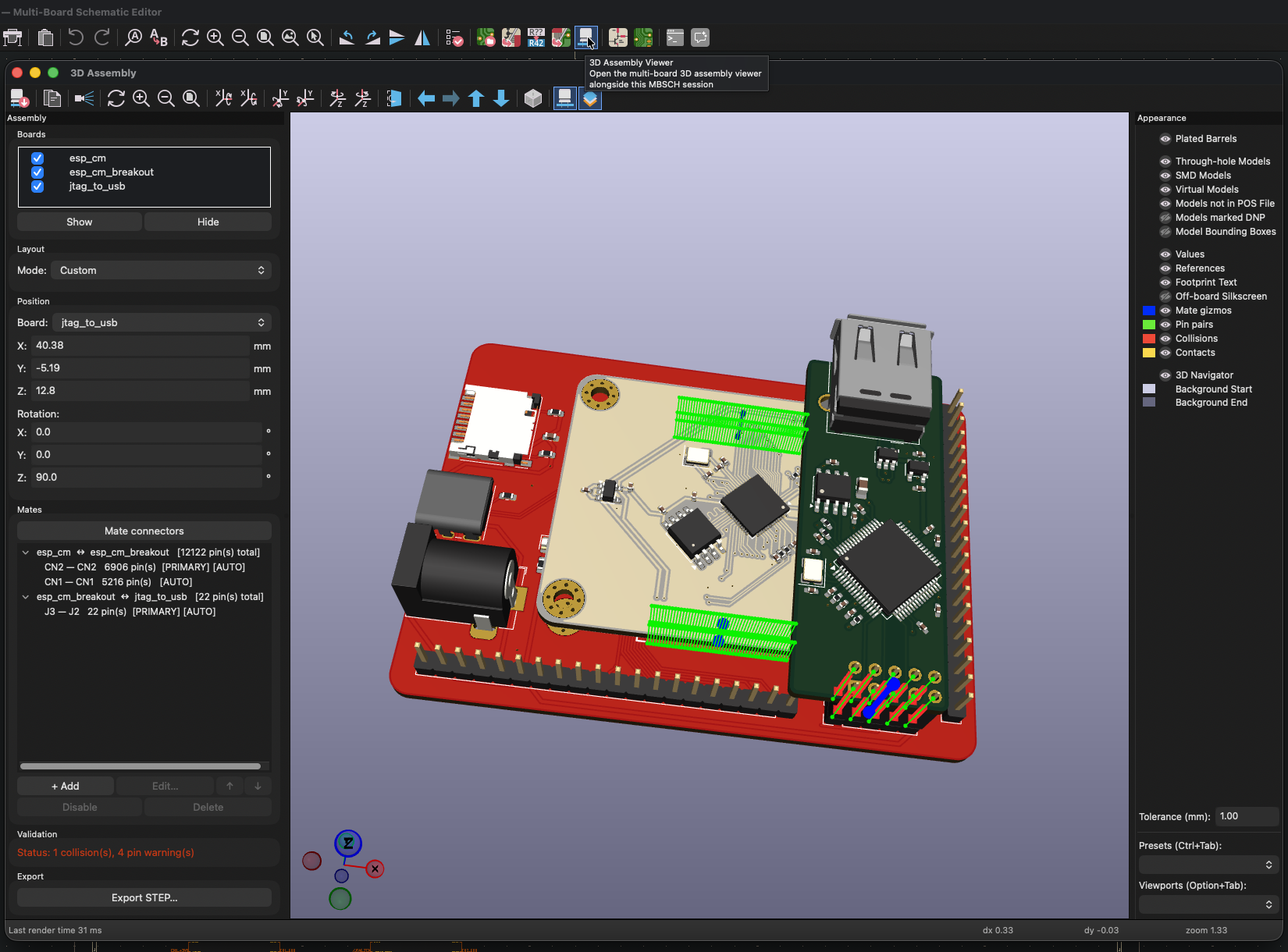
Mate connections
When two boards mate via a connector pair (a header on one board plugged into a socket on another), the viewer positions the boards so the mating connectors line up. Mates are auto-derived from:
- Cross-board nets on the MBS: any cross-board net with endpoints on two different sub-projects defines a candidate connector pair. Refresh and wire your nets on the MBS first; new pairs appear in the viewer on the next reload.
- Footprint pad positions: for each candidate pair, pins are matched 1:1 by physical pad position on each footprint, sorted lexicographically by (X, Y). Net assignment isn't used for the per-pin matching — geometry is.
- Same-name power nets (e.g.
GND,VCC): grouped together so the viewer doesn't mis-pair pins when multiple connectors share a ground or power net.
Collision threshold
The Collision threshold field in the Appearance Controls panel sets how much mesh overlap is acceptable between mated boards. Default is 0.5 mm.
When two parts intersect, the viewer measures the thinnest dimension of the intersection volume:
- Below the threshold → Contact: Expected for normal connector seating, where the plug penetrates the socket by a designed mating depth.
- Above the threshold → Collision: The boards or components are physically interfering and won't assemble.
Tune this when your connectors have an unusually deep mating depth, or when tight component clearances flag as false collisions. The value is saved to the container .kicad_pro and persists across sessions.